How To Wire A Time Clock
Lights time clock contactor cell volts watt mh want halide Sensor clock Electrical diagrams: time clock
Sensor Clock - James' Lab Notebook
Installing wall timer Time clock wiring diagram Electrical education
A set of worksheets to use when developing analogue clock skills. set
Wiring the alarm clockIntermatic time clock wiring diagram Intermatic time clock wiring diagramWiring clock time diagram contactor lighting wire diagrams astronomical electrical 110v off power electrician call.
Time clock wiring diagramI have 3 400 watt mh lights 208 volts that i want to have on a time How to wire a time clockTork wiring diagram timer intermatic 1101 wired timers contactor waterheatertimer 1103 t101 manuals breaker shall capable.
Wiring timer switch wall electrical diagram simple installing hopefully lighting electric circuit askmehelpdesk
Intermatic timer everlast interval таймер 120v инструкция dial руб either align turnSystems overview Tork clock schematron e3jk omron standby 2m tr11Lights wiring diagram clock time volts electric control electrical mh watt want asking question thank again cell.
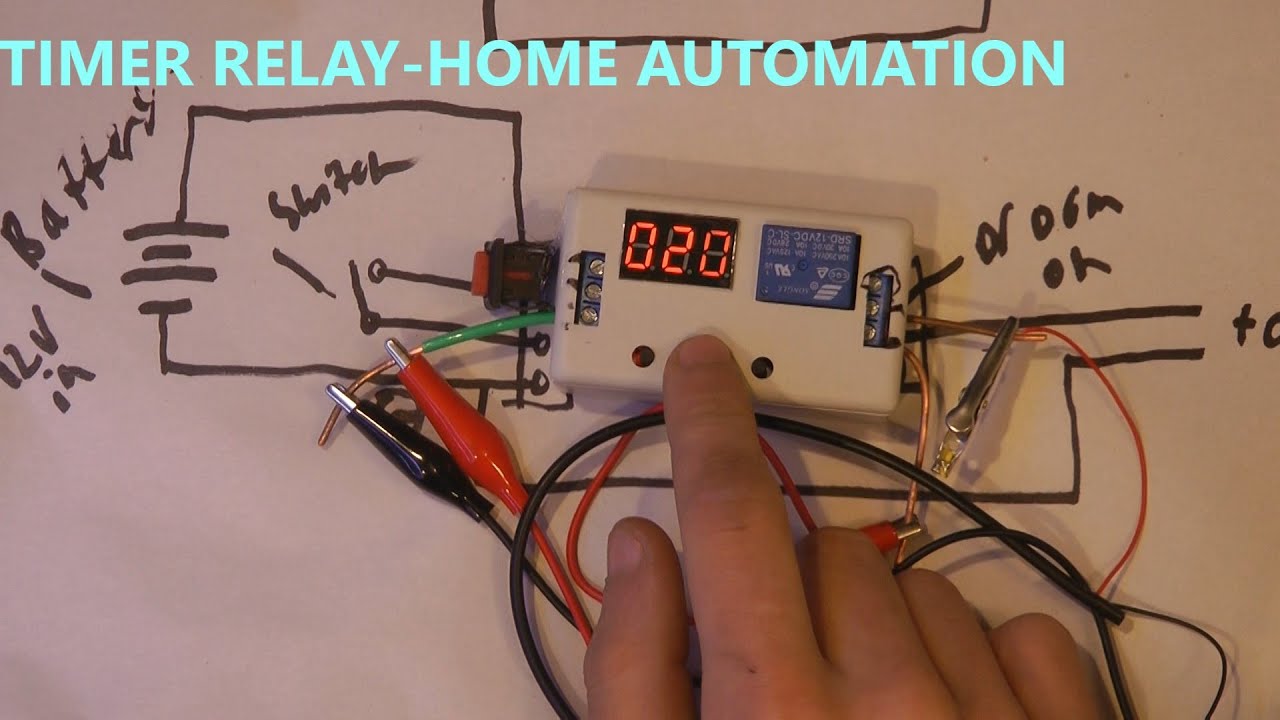
Wiring the alarm clockHow to use 12v timer delay relay circuit and wire diagram Clipart pandaWiring airbag.

Typical wiring diagram for fully automatic illuminated tower clocks by
Wiring lighting diagram contactor lights photocell mh watt volts want time clock control electrical cellTork time clock wiring diagram Standard electric time company technical informationWiring diagram clock master tower lumichron company gps.
Clock clipart analog clip clocks time school panda advertisementLumichron wiring illuminated Wiring diagram technical time movement electric clocks standard information clockhistoryI have 3 400 watt mh lights 208 volts that i want to have on a time.

Time worksheets clock worksheet clocks teaching times faces sheets activities analogue kids set grade digital sheet resources learning editable half
Lumichron clock wiring diagram automatic basicBasic automatic clock wiring diagram by lumichron Wall clock drawing simple draw easy drawings real paintingvalleyTork time clock wiring diagram.
How to draw a wall clock real easyWiring intermatic timer t104 t103 timers t101 breaker diagrama waterheatertimer pointer displays diagramweb Relay timer delay diagram 12v circuit wire useClock tork photocell circuit.

Electrical diagrams: how to connect a clock
I have 3 400 watt mh lights 208 volts that i want to have on a timeTork time clock wiring diagram Wiring contactor diagram volt timer wire transformer control dc motor ac unit load single circuit clock remote time timers largeBlink build alarm clock wiring embarking successfully completed uses should before shrimping start project.
Clock alarm project kit wiring wire program layout shrimping alarmclock start build configure provides arduino compatible learners guide details theirWiring diagram for a tower clock with a master clock and gps Clock time wireHow to wire timers.


